Maslow 2022 Control Board
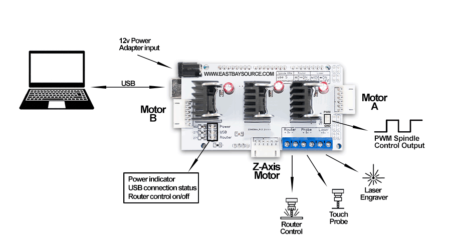
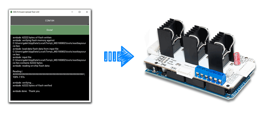
Control Board firmware installation
- Download and unzip the latest EBS Firmware Upload Tool from HERE (choose the version suitable for your operating System)
- Launch the tool and make sure the Control Board is connected to your computer's USB port.
- Select the correct port, click upload and wait for a few seconds until it finishes uploading the firmware.
Automatic Router On/Off (optional add-on)
NOTE: The following functionality is not needed for the machine to run properly, most users will just turn the router On/Off manually.
Adding a relay to turn your router on/off via G-code commands.
What you need:
| 1 - SSR with Heat sink |
 |
| 2 - Extension cord |  |
IMPORTANT. The relay and extension cord used must be rated for your application.
Inductive loads typically require 2-3 times the runtime amperage when power is first applied to the device.
For instance, a motor rated at 10 Amps, will often draw 20-30 amps just to get the motor's shaft in motion.
What to look for when buying a SSR
Check the SSR (solid state relay) specifications to ensure it is compatible and tolerances are within limits. 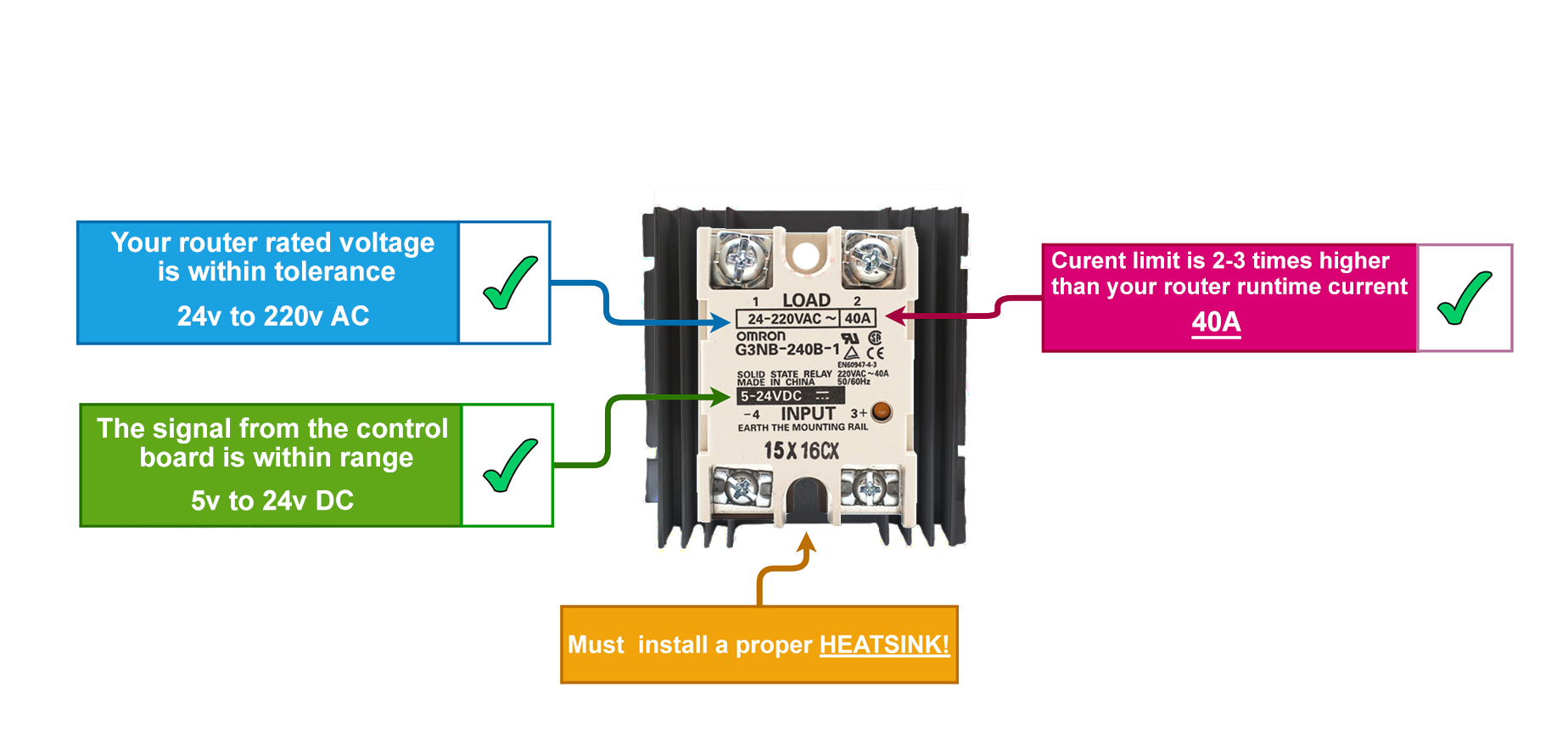
Putting it all together
To avoid splicing the router power cord, we'll use an extension cord instead.
You will need to identify the LIVE wire in the cord which is the one to splice (usually the brown/black in the US).
Using a multimeter to do a continuity test is the easiest way to identify and splice the correct wire
 |
WARNING - Use extreme caution when working with mains-voltage as it could be dangerous | |
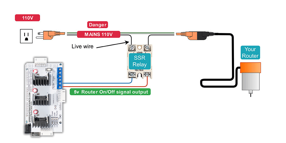
- Use M3/M5 g-code commands to turn the router On/Off.
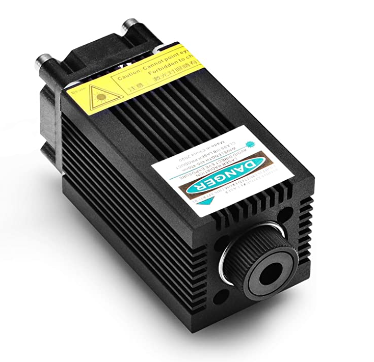
Laser Engraver (optional add-on)
Using a Laser Engraver module in place of the Router.
What you need:
| 1 - Laser Diode |
 |
| 2 - Wire |
 |
| 3 - Power adapter | 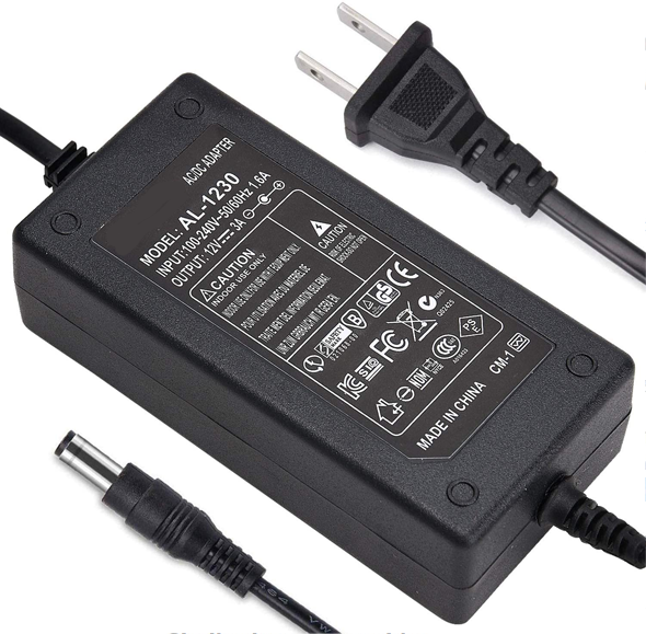 |
| 4. Eye protection |  |
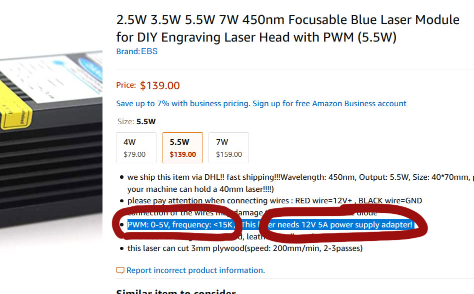
Choosing a compatible Laser Module
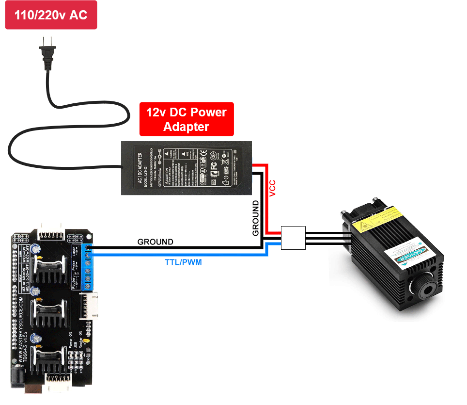
- Laser engravers usually have 3 wire connectors, VCC, TTL/PWM and GND.
- EBS Control Board outputs a Hi/Low 5v signal from its laser output, it will turn full On (100% duty cycle) laser diodes with an input range from 0 to 5v TTL/PWM.
|
 |
Wiring diagram
- Use M106/M107 g-code commands to turn laser On/Off